0CTF/TCTF 2019 Quals: Sixology write-up
Sixology was a reverse task which 2 teams managed to solve during the CTF. You can find summary section (TL;DR) as well as some links in the end of write-up.
In this task we got 2 files:
0ctf2019.dll: PE32+ executable (DLL) (GUI) x86-64, for MS Windows
binary: data
DLL reverse engineering
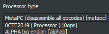
Let’s open DLL in IDA. There is no interesting code in DllEntryPoint and the only other exported symbol is some structure LPH. Here is how it looks:
.data:0000000180009000           public LPH
.data:0000000180009000 LPH       db 0BCh ; ј
.data:0000000180009001           db    2
...
.data:0000000180009018           dq offset off_1800065E8 ; "0ops"
.data:0000000180009020           dq offset off_1800065F8 ; "0CTF2019 ( Processor )"
.data:0000000180009028           dq offset off_1800065D8 ; "bF'@"
.data:0000000180009030           dq offset sub_180001000
.data:0000000180009038           dq offset off_1800062F0
...
Hmm, processor… I immediately thought that it may be a processor module for IDA. You can check imports to be extra sure about this: there are 48 imports from module called IDA.
Let’s copy this DLL in ida/procs folder, load binary and see what happens.
And after loading… <!–
ROM:00000000    6666666_________ _____________666666666, 0x66546330
ROM:00000008    6666666_________ ___________6666666666, 0x66546334
ROM:00000010    6666666_________ _______66666, 0x66546372 ;; 'B'
ROM:00000018    6666666_________ ____________6666, 0x665468B0
ROM:00000020    6666666_________ _____________66666, 0x66546F90
ROM:00000028    6666666_________ ___________6666666, 0x66546BB8
ROM:00000030    666666666____________ loc_34, _______66666
ROM:00000030
ROM:00000034
ROM:00000034 loc_34:                          ;; CODE XREF: ROM:00000054↓j
ROM:00000034    66666666____________ ______66666666, ____________6666, _____________666666666
ROM:00000038    666666666_____________ _______6666, op1
ROM:0000003C    66666666____________ ______66666666, _____________66666, _____________666666666
ROM:00000040    666666666_____________ ________666666, op1
ROM:00000044    666666666_________ sub_1E0
ROM:00000048    66666666____________ ______66666666, ___________6666666, _____________666666666
ROM:0000004C    66666_____ _______6666, op1 ;; [0x000888] read only
ROM:00000050    66666666____________ _____________666666666, _____________666666666, ___________6666666666
ROM:00000054    6666_____ loc_34
ROM:00000054
ROM:00000058    6666666_________ _______66666, 0x66546372 ;; 'B'
ROM:00000060    6666666_________ __________6666, 0x66546331
–>
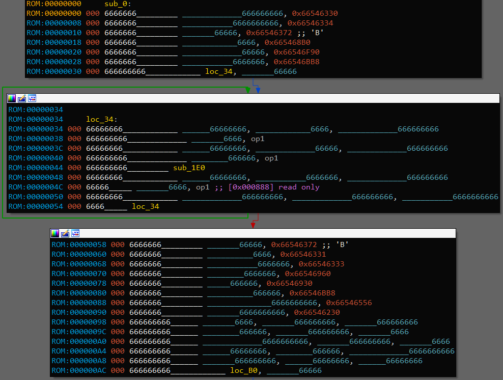
W00t. Seems that all mnemonics as well as register names are obfuscated.
Since we confirmed that the DLL is an IDA processor module, let’s look for the interface documentation. Simple ida lph query gives us a link to processor_t structure description. Sadly, it seems a bit outdated but all needed info is still there. Using IDA SDK may be more convenient.
First of all, LPH export is a pointer to processor_t structure which contains all needed info for IDA to use this processor module. I’ve ended up with following structure:
struct processor_t
{
  uint32 version;
  uint32 id;
  uint32 flag;
  uint32 flag2;
  uint32 cnbits;
  uint32 dnbits;
  void *psnames;
  void *plnames;
  void *assemblers;
  void *_notify;
  void *reg_names;
  uint32 regs_num;
  uint32 reg_first_sreg;
  uint32 reg_last_sreg;
  uint32 segreg_size;
  uint32 reg_code_sreg;
  uint32 reg_data_sreg;
  unsigned __int64 codestart;
  unsigned __int64 retcodes;
  uint32 instruc_start;
  uint32 instruc_end;
  void *instruc;
  unsigned __int64 tbyte_size;
  unsigned __int8 real_width[4];
  uint32 icode_return;
  void *unused_slot;
};
and following processor description:
.data:0000000180009000         public LPH
.data:0000000180009000 LPH     dd 700                  ; DATA XREF: .rdata:off_1800080C8↑o
.data:0000000180009000                                 ; version
.data:0000000180009004         dd 87E3h                ; id
.data:0000000180009008         dd 8100Eh               ; flag  PR_NO_SEGMOVE|PR_TYPEINFO|PR_RNAMESOK|PR_DEFSEG32|PR_USE32
.data:000000018000900C         dd 0                    ; flag2
.data:0000000180009010         dd 8                    ; cnbits
.data:0000000180009014         dd 8                    ; dnbits
.data:0000000180009018         dq offset psnames
.data:0000000180009020         dq offset plnames
.data:0000000180009028         dq offset assemblers
.data:0000000180009030         dq offset _notify
.data:0000000180009038         dq offset reg_names
.data:0000000180009040         dd 40                   ; regs_num
.data:0000000180009044         dd 38                   ; reg_first_sreg
.data:0000000180009048         dd 39                   ; reg_last_sreg
.data:000000018000904C         dd 0                    ; segreg_size
.data:0000000180009050         dd 38                   ; reg_code_sreg
.data:0000000180009054         dd 39                   ; reg_data_sreg
.data:0000000180009058         dq offset codestart
.data:0000000180009060         dq 0                    ; retcodes
.data:0000000180009068         dd 0                    ; instruc_start
.data:000000018000906C         dd 32                   ; instruc_end
.data:0000000180009070         dq offset instruc
.data:0000000180009078         dq 0                    ; tbyte_size
.data:0000000180009080         db 0, 4, 8, 10h         ; real_width
.data:0000000180009084         dd 29                   ; icode_return
.data:0000000180009088         dq 0                    ; unused_slot
Most important things here are _notify - function pointer, reg_names - array of register names, and instruc - array of instruc_t structures { char* name, uint32 feature }. Also we can see that register 38 is code segment register - cs, and register 39 is data segment register - ds.
instruc array can be useful: instruc_t has a feature field which contains some flags describing the instruction:
instruc  instruc_t <offset aOp0, 0>; 0
                                 ; DATA XREF: .data:0000000180009070↑o
         instruc_t <offset aOp1, 0>; 1 ; "op0" ...
         instruc_t <offset aOp2, CF_USE1>; 2
         instruc_t <offset aOp3, CF_CHG2 or CF_USE1>; 3
         instruc_t <offset aOp4, CF_CHG1 or CF_CHG2>; 4
         instruc_t <offset aOp5, 0>; 5
         instruc_t <offset aOp6, 0>; 6
         instruc_t <offset aOp7, CF_USE1 or CF_USE2>; 7
         instruc_t <offset aOp8, CF_CHG1 or CF_USE2 or CF_USE3>; 8
         instruc_t <offset aOp9, 0>; 9
         instruc_t <offset aOp10, 0>; 10
         instruc_t <offset aOp11, CF_CHG1 or CF_USE2>; 11
         instruc_t <offset aOp12, CF_CHG1 or CF_USE2 or CF_USE3>; 12
         instruc_t <offset aOp13, 0>; 13
         instruc_t <offset aOp14, CF_CHG1 or CF_USE2 or CF_USE3>; 14
         instruc_t <offset aOp15, 0>; 15
         instruc_t <offset aOp16, CF_CHG1 or CF_USE2>; 16
         instruc_t <offset aOp17, CF_CALL or CF_USE1>; 17
         instruc_t <offset aOp18, 0>; 18
         instruc_t <offset aOp19, CF_USE1 or CF_JUMP>; 19
         instruc_t <offset aOp20, CF_CHG1 or CF_USE2 or CF_USE3>; 20
         instruc_t <offset aOp21, 0>; 21
         instruc_t <offset aOp22, 0>; 22
         instruc_t <offset aOp23, CF_USE1 or CF_JUMP>; 23
         instruc_t <offset aOp24, CF_CHG1 or CF_CHG2 or CF_USE3 or CF_USE4>; 24
         instruc_t <offset aOp25, 0>; 25
         instruc_t <offset aOp26, CF_USE1 or CF_USE2 or CF_USE3 or CF_JUMP>; 26
         instruc_t <offset aOp27, CF_CHG1 or CF_USE2 or CF_USE3>; 27
         instruc_t <offset aOp28, 0>; 28
         instruc_t <offset aOp29, CF_STOP>; 29
         instruc_t <offset aOp30, CF_USE1 or CF_USE2 or CF_JUMP>; 30
         instruc_t <offset aOp31, CF_CHG1 or CF_USE2>; 31
CF_USE and CF_CHG are not very useful while CF_STOP, CF_JUMP and CF_CALL are more interesting. CF_STOP indicates ret instruction with opcode 29, CF_CALL - call instruction with opcode 17, and CF_JUMP gives us 2 types of (maybe) conditional jumps, 26 and 30, as well as 2 types of (maybe) unconditional jumps - 19 and 23. Seems pretty strange to have 2 kinds of plain jmp, what does it mean?
Next thing, I renamed all registers and opcodes:
reg_names = ['r{}'.format(i) for i in range(40)]
for i, new_name in enumerate(reg_names):
    addr = 0x00000001800062F0 + i * 8       # reg_names
    addr = Qword(addr)
    for j in range(len(new_name)):
        PatchByte(addr + j, ord(new_name[j]))
    PatchByte(addr + len(new_name), 0)
    MakeUnknown(addr, 1, 0)
    create_strlit(addr, BADADDR)

op_names = ['op{}'.format(i) for i in range(32)]
for i, new_name in enumerate(op_names):
    addr = 0x00000001800090A0 + i * 16       # instruc
    addr = Qword(addr)
    for j in range(len(new_name)):
        PatchByte(addr + j, ord(new_name[j]))
    PatchByte(addr + len(new_name), 0)
    MakeUnknown(addr, 1, 0)
    create_strlit(addr, BADADDR)
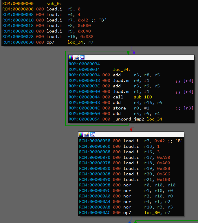
After that, disassembled code starts to look way more manageable. By looking at the disassembled binary code we can note that not all instructions are used. There are 32 supported instructions, but binary uses only 20 of them, 0 1 6 9 10 13 15 18 21 22 25 28 remain unused, so we don’t need to understand their meaning.
Let’s go after the last (and most) interesting thing from LPH - function _notify at address 0x180001000.
_notify
From IDA SDK we get the prototype: __int64 __fastcall notify(void *user_data, event_t notification_code, va_list va), where event_t is enumeration of all possible events. For each event it is documented which arguments exactly are passed through va_list and what you are supposed to do. After applying enum and renaming called functions, most interesting part of _notify for us is this one:
...
      case ev_ana_insn:
        return ana(*va);
      case ev_emu_insn:
        v8 = emu(*va);
        v9 = -1i64;
        if ( v8 )
          v9 = 1i64;
        return v9;
      case ev_out_header:
      case ev_out_footer:
      case ev_out_segstart:
        goto LABEL_8;
      case ev_out_insn:
        out_insn(*va);
        return 1i64;
      case ev_out_mnem:
        out_mnem(*va);
LABEL_8:
        result = 1i64;
        break;
      case ev_out_operand:
        v10 = out_operand(*(outctx_t **)va, *((op_t **)va + 1));
...
Let’s see what happens here. ana is the first analysis step. It takes raw instruction bytes and fills the insn_t structure which contains internal instruction ID, information about instruction operands (their types, properties etc.) and other info.
Next step is emu. While ana only parses the instruction, emu continues analysis based on instruction meaning. For example, if we have instruction mov r0, [1234] then emu is supposed to make a data reference (data xref) from that instruction to address 1234. Basically, emu needs to tell IDA about everything that instruction performs as well as side effects (one “side effect” of mov instruction is that it passes execution to the next instruction, so emu adds this “flow reference” and IDA is then able to produce function CFG).
Last step is when everything is ready and IDA asks processor to show information on the screen. It is a bit more complicated than just using printf: processor can modify text, set different styles, and tell IDA that printed chunk of text is some special object like address.
ana
ana prototype is __int64 __fastcall ana(insn_t *insn), where I defined insn_t like this:
struct insn_t
{
  ea_t cs;
  ea_t ip;
  ea_t ea;
  uint16 itype;
  uint16 size;
  union {
    uint32 auxpref;
    uint16 auxpref_u16[2];
    uint8 auxpref_u8[4];
  } auxprefs;
  char segpref;
  char insnpref;
  int16_t flags;
  op_t ops[8];
};
op_t defines an operand, it looks like this:
struct op_t
{
  uchar n;
  OP_TYPE type;
  char offb;
  char offo;
  uchar flags;
  OP_DTYPE dtype;
  union {
    uint16 reg;
    uint16 phrase;
  };
  union {
    uint16 low;
    uint16 high;
  } value;
  union {
    uint16 low;
    uint16 high;
  } addr;
  union {
    uint16 low;
    uint16 high;
  } specval;
  char specflag1;
  char specflag2;
  char specflag3;
  char specflag4;
};
OP_TYPE and OP_DTYPE are enums crafted from SDK magic values. For example, OP_TYPE:
enum OP_TYPE : __int8
{
  O_VOID = 0x0,
  O_REG = 0x1,
  O_MEM = 0x2,
  O_PHRASE = 0x3,
  O_DISPL = 0x4,
  O_IMM = 0x5,
  O_FAR = 0x6,
  O_NEAR = 0x7,
  O_IDPSPEC0 = 0x8,
  O_IDPSPEC1 = 0x9,
  O_IDPSPEC2 = 0xA,
  O_IDPSPEC3 = 0xB,
  O_IDPSPEC4 = 0xC,
  O_IDPSPEC5 = 0xD,
};
These are all structures we need. Not so much can be taken from ana at this point besides operand types. There is one interesting thing though. Most instructions are 4 bytes long but there is one that is 8 bytes long, 11. Here is the code handling this instruction:
    case 11:
      v6 = insn&->ea + 4;
      v11 = O_VOID;
      if ( get_bytes(&v11, 4i64, v6, 0i64, O_VOID) != 4 )
        return 0i64;
      v7 = insn_bytes;
      v8 = v11;
      insn&->ops[0].type = O_REG;
      insn&->ops[0].dtype = DT_DWORD;
      insn&->ops[1].type = O_IMM;
      insn&->ops[1].dtype = DT_DWORD;
      insn&->ops[0].reg_union.reg = (v7 >> 27) & 0x1F;
      insn&->ops[1].value_union.value = v8 ^ 0x46544330;
      insn&->size += 4;
      return insn&->size;
Additional 4 bytes form the second operand which is xored with 0x46544330, i.e., '0CTF'. It means that immediate values are stored in binary in obfuscated form.
Another interesting piece of code is this one:
    case 3:
    case 31:
      insn&->ops[0].type = O_REG;
      v5 = (insn_bytes& >> 19) & 3;
      insn&->ops[0].reg_union.reg = (insn_bytes& >> 27) & 0x1F;
      insn&->ops[0].dtype = (insn_bytes& >> 19) & 3;
      switch ( (insn_bytes& >> 17) & 3 )
      {
        case 1u:
          insn&->ops[1].type = O_PHRASE;
          insn&->ops[1].dtype = v5;
          insn&->ops[1].reg_union.phrase = (insn_bytes& >> 22) & 0x1F;
          break;
        case 2u:
          insn&->ops[1].type = O_DISPL;
          insn&->ops[1].dtype = v5;
          insn&->ops[1].addr_union.addr = insn_bytes& & 0xFFF;
          insn&->ops[1].reg_union.phrase = (insn_bytes& >> 22) & 0x1F;
          break;
        case 3u:
          insn&->ops[1].type = O_MEM;
          insn&->ops[1].dtype = v5;
          insn&->ops[1].addr_union.addr = insn_bytes& & 0xFFF;
          break;
      }
      return insn&->size;
Based on operand types and documentation, we deduce that these two instruction are working with memory in 3 modes: [reg], [reg+imm], [imm]. It’s pretty safe to assume that one of this is load and other is store (I’ll call them load.m and store.m later to denote memory access).
Since there is nothing more handy in ana, let’s move to the next step, emu.
emu
emu prototype is the same as ana’s: __int64 __fastcall emu(insn_t *insn). Only difference is that insn is already filled.
First things we see in emu are these ones:
  if ( _bittest(&feature, 8u) )                 // CF_USE1
    emu_internal(insn&, insn&->ops, 1);
  if ( _bittest(&feature, 9u) )                 // CF_USE2
    emu_internal(insn&, &insn&->ops[1], 1);
...
  if ( feature & CF_CHG3 )
    emu_internal(insn&, &insn&->ops[2], 0);
  if ( feature & CF_CHG4 )
    emu_internal(insn&, &insn&->ops[3], 0);
emu_internal
Looking into emu_internal, it actually adds different kinds of references. There is one particularly important piece in this function, default switch cases:
  switch ( op_type )
  {
...
    default:
      if ( op_type == O_IDPSPEC1 && insn->itype == 26 )
      {
...
        if ( get_switch_info(&Dst, v7) <= 0 )
        {
          v8 = insn&->ops[2].addr_union.addr;
          v9 = get_dword(insn&->ops[2].addr_union.addr) ^ 0x46544330;
          if ( v9 <= 0x80 )
          {
            LODWORD(v21) = insn&->ops[1].addr_union.addr;
            v10 = insn&->ops[0].reg_union.reg;
...
            set_switch_info(v11, &Dst);
            create_switch_table(insn&->ea, &Dst);
            create_switch_xrefs(insn&->ea, &Dst);
          }
        }
      }
      break;
  }
It makes clear that instruction with opcode 26 is switch.
Back to emu, next part:
  v5 = insn&->itype;
  if ( v5 == 3 )
  {
    *(_QWORD *)&a3.d0 = *(_QWORD *)&insn&->ops[1].n;
    a3.addresses.begin = *(_DWORD **)&insn&->ops[1].value_union.value;
    a3.addresses.length = *(_QWORD *)&insn&->ops[1].specval_union.specval;
    if ( BYTE1(a3.d0) == 2 )                    // O_MEM
    {
      mem_addr = (unsigned __int64)a3.addresses.begin >> 32;
    }
    else
    {
...
      v7 = get_possible_values(&a1, insn&, (op_t *)&a3, &values, 0);
      sub_1800036A0((__int64 **)&a1, &v22, *(_QWORD *)a1, (__int64)a1);
      operator delete(a1);
      if ( !v7 )
      {
        qfree((qvector_t *)values.addresses.begin);
        goto LABEL_36;
      }
      LODWORD(mem_addr) = values.d0;
      qfree((qvector_t *)values.addresses.begin);
    }
    if ( insn&->ops[1].type == O_DISPL )
      LODWORD(mem_addr) = insn&->ops[1].addr_union.addr + mem_addr;
    if ( is_rodata((unsigned int)mem_addr) )
    {
      qsnprintf(&v26, 256i64, "[%#08x] read only", (unsigned int)mem_addr);
      LOBYTE(v8) = 1;
      set_cmt(insn&->ea, &v26, v8);
    }
  }
Look at this qsnprintf, we definitely saw it before: when we first tried to open binary, ROM:0000004C 66666_____ _______6666, op1 ;; [0x000888] read only. Note that opcode is 3, we already know that it is either load.m or store.m. There is no need to make warning about reading read-only memory, so we can assume that opcode 3 is store.m and 31 is load.m.
What this code is trying to do as a whole is to get somehow target memory address and check that it is not in .rodata section. If operand type is O_MEM then address is just an immediate value, otherwise the register is used so we need to get it’s possible values somehow. That what function get_possible_values is doing, as we’ll see next.
get_possible_values
This is the most complex and most important part of processor for us. Let’s look at the very beginning:
char __fastcall get_possible_values(void *a1, insn_t *insn, op_t *a3, possible_values_t *values, int a5)
{
  // [COLLAPSED LOCAL DECLARATIONS. PRESS KEYPAD CTRL-"+" TO EXPAND]

  values& = values;
  insn& = insn;
  switch ( (unsigned __int8)a3->type )
  {
    case O_REG:
    case O_IDPSPEC0:
      result = track_possible_values_cfg(a1, insn, insn->ea, a3->reg_union.reg, values, a5);
      break;
...
  }
  return result;
}
In case of O_REG it just calls some internal function that I conveniently called track_possible_values_cfg. It is almost 450 lines long and consists of very valuable code. Note that second parameter is insn, third is ea and fourth is reg_num
track_possible_values_cfg
...
  while ( 1 )
  {
    v16 = get_flags_ex(v15->ea, 0i64);
    if ( (v16 >> 12) & 1 || !(v16 & CF_HLL) )
      break;
    if ( (unsigned int)decode_prev_insn(&prev_insn, v15->ea) == -1 )
      goto LABEL_125;
LABEL_31:
    v15 = &prev_insn;
    if ( (prev_insn.ops[0].type == O_REG || prev_insn.ops[0].type == O_IDPSPEC0)
      && prev_insn.ops[0].reg_union.reg == (_DWORD)reg_num& )
    {
      switch ( prev_insn.itype )
...
OK, lots of things to note here. First of all, while (1). Why is it here? I don’t know but I don’t like it.
In this while we are taking current address and decode previous instruction. If first operand of this instruction is the same register that we want to know values of, we go deeper into big switch based on previous instruction opcode. Let’s take a look at the code in this switch:
        case 4u:
        case 16u:
          v10 = get_possible_values(v8, &prev_insn, &prev_insn.ops[1], &a4a, a6 + 1);
          goto LABEL_105;
OK.
        case 8u:
        case 12u:
        case 14u:
        case 20u:
        case 24u:
        case 27u:
...
          v25 = &prev_insn.ops[1];
          v26 = &prev_insn.ops[2];
          if ( prev_insn.itype == 24 )
          {
            v25 = &prev_insn.ops[2];
            v26 = &prev_insn.ops[3];
          }
          if ( !get_possible_values(v8, &prev_insn, v25, &valuesa, a6 + 1)
            || !get_possible_values(v8, &prev_insn, v26, &v47, a6 + 1) )
          {
            goto LABEL_104;
          }
          switch ( prev_insn.itype )
          {
            case 8u:
              a4a.d0 = v47.d0 + valuesa.d0;
              goto LABEL_95;
            case 12u:
              v27 = ~(valuesa.d0 | v47.d0);
              goto LABEL_94;
            case 14u:
              v27 = valuesa.d0 - v47.d0;
              goto LABEL_94;
            case 20u:
              if ( prev_insn.ops[0].specflag1 )
              {
                if ( prev_insn.ops[0].specflag1 == 1 )
                  a4a.d0 = valuesa.d0 == v47.d0;
                else if ( prev_insn.ops[0].specflag1 == 2 )
                  a4a.d0 = valuesa.d0 > v47.d0;
              }
              else
                a4a.d0 = valuesa.d0 < v47.d0;
              goto LABEL_95;
            case 24u:
              v27 = v47.d0 / (unsigned int)valuesa.d0;
              goto LABEL_94;
            case 27u:
              Dst[0] = 0;
              memset(&Dst[1], 0, 0xFFui64);
              v57[0] = 0;
              memset(&v57[1], 0, 0xFFui64);
              qsnprintf(Dst, 255i64, "%d", (unsigned int)valuesa.d0);
              qsnprintf(v57, 255i64, "%d", (unsigned int)v47.d0);
              str1 = Dst;
              str2 = v57;
              str_i = 0i64;
              if ( !Dst[0] )
                goto LABEL_82;
              break;
            default:
              goto LABEL_95;
          }
          break;
Now this is very sweet, we can immediately say what these instructions do. Opcode 8 is add, 12 is nor, 14 is sub, 20 is cmp with 3 modes, 24 is div, and 27 is strcmp with 3 modes as well (you can check usages of str1 and str2 to see that this is the case). Note that strcmp does not really compare strings, it just compares two numbers lexicographically, i.e., compares two strings obtained by sprintf(buf, "%d", opK) where opK is either op1 or op2.
After the CTF, players noted in IRC that, for opcode
div, order of used operands is kinda swapped (confirmed in source code here). For example, insubyou doop2 - op3but indivit isop4 / op3. This is an error in task because actuallydivisop3 / op4which can be confirmed from binary logic. Thankfully I didn’t pay enough attention while reversing this part and didn’t notice the reversed order.
Next there are cases for opcodes 11 and 31, from which you can conclude that 11 is load.i (loads immediate in register, remember, this one is 8 bytes long) and confirm that 31 is indeed load.m.
That’s all with this switch. Next, it is checked if we are interested in possible values of second operand instead of first: if ( prev_insn.ops[1].type == O_REG && prev_insn.ops[1].reg_union.reg == (_DWORD)reg_num& ). In this case, only 2 instructions are checked: 4 and 24. We already know that 24 is div and op1 = op3 / op4. Naturally, it occures that op2 = op3 % op4.
What about instruction 4? Let’s investigate it. We already saw code mentioning that instruction in first big switch:
        case 4u:
        case 16u:
          v10 = get_possible_values(v8, &prev_insn, &prev_insn.ops[1], &a4a, a6 + 1);
          goto LABEL_105;
Result op1 value from instruction 4 is equal to initial op2 value. Next:
      if ( prev_insn.itype == 4 )
        v10 = get_possible_values(v8, &prev_insn, prev_insn.ops, &a4a, a6 + 1);
Result op2 value is equal to initial op1 value. What it means is that instruction with opcode 4 is swap or xchg.
Also we can say that instruction 16 is load.r because it changes only first operand (you can see it in this instruction feature flags) and it will be equal to second operand.
emu
Going back to emu, a bit lower we see the following code:
  is_jmp = 0;
  v12 = insn&->itype;
  if ( v12 == 19 )
  {
LABEL_42:
    is_jmp = 1;
    goto LABEL_43;
  }
  if ( v12 == 30 )
  {
...
    v13 = get_possible_values(&a1, insn&, insn&->ops, &values, 0);
...
    if ( v13 )
    {
      v14 = values.d0;
      qfree((qvector_t *)values.addresses.begin);
      if ( v14 == 1 )
        goto LABEL_42;
    }
    else
      qfree((qvector_t *)values.addresses.begin);
  }
LABEL_43:
  if ( feature & CF_STOP || is_jmp )
    v15 = 0;
  else
  {
    v15 = 1;
    add_cref(insn&->ea, insn&->ea + insn&->size, 21i64);// fl_F
  }
add_cref type 21 is fl_F - flow reference, which means that instruction may pass execution to next instruction without jumping anywhere else. So v15 means exactly this - next instruction after the end of current one may be executed next. As we know, CF_STOP means ret instruction which makes perfect sense - instruction next to ret won’t be executed after ret by any means. We can deduce that instruction 19 is jmp because unconditional jump can’t execute next instruction in the terms of ordinary flow - it can only jump to next instruction, which is different kind of reference. Instruction 30 is more interesting: we know that it is some kind of conditional jump. Here emu tries to deduce possible values of used conditional register, and if it is always non-zero then it simplifies that jump to unconditional jump, i.e., does not make flow reference to next instruction. What that means for us is that instruction 30 is jnz.
Next, near the end we see another feature of this analysis step, stack pointer calculating:
    v17 = get_func(v16);
    if ( v17 )
    {
      v18 = get_sp_change(insn&);
      if ( v18 )
        add_auto_stkpnt(v17, insn&->ea + insn&->size, v18);
    }
From add_auto_stkpnt we know that v18 should be SP change on this instruction. What’s inside the get_sp_change?
get_sp_change
  itype = insn->itype;
  if ( itype == 2 )
    return -8 - insn->ops[0].value_union.value;
Looks like opcode 2 means instruction which is allocating place on stack. In the binary there are two functions, and instruction 2 is the first one in each of them. We can think about it like this: it prepares function stack frame. Let’s call it enter.
  if ( itype == 5 )
  {
    v6 = get_func(insn->ea);
    if ( v6 )
      return (unsigned int)-get_spd(v6, insn&->ea);
    return 0i64;
  }
If we are in function then this opcode reverts back SP to the value it had before executing first function instruction (SP diff = 0). Doing the same things as with instruction 2, you can see that 5 is used in the very end of both functions. Looks like it is an anti-enter function - leave.
  if ( itype != 8 && itype != 14
    || insn->ops[0].type != O_REG
    || insn->ops[0].reg_union.reg != 31
    || insn->ops[1].type != O_REG
    || insn->ops[1].reg_union.reg != 31 )
  {
    return 0i64;
  }
Only other possibility when we can calculate SP diff for given instruction is when it is either add or sub in th form add/sub r31, 31, ???. We can conclude that r31 is sp.
That’s all with the emu function.
Recap
Let’s see what we already know:
opcodes: [0..31]
not used: 0 1 6 9 10 13 15 18 21 22 25 28
2  - enter
3  - store.m
4  - swap
5  - leave
7  - ?
8  - add
11 - load.i
12 - nor
14 - sub
16 - load.r
17 - call
19 - jmp
20 - cmp
23 - _uncond_jmp2 (?)
24 - div
26 - switch
27 - strcmp
29 - ret
30 - jnz
31 - load.m
Nice, meaning of 18 instructions is definite, about another 1 we know at least something, and we don’t know anything about only 1 more.
out_operand
There is one interesting detail in this function:
    case O_IMM:
      v13 = op&->dtype;
      v18 = 5;
      v19 = v13;
      v20 = op&->value_union.value ^ 0x66546330;
      a1->vt->out_value(a1, (const op_t *)&v17, 68);
      break;
Another XORing, this time with '0cTf'. Since this is output function, we don’t want our constants to be xored with something, so we patch out this xor.
Another thing to note about out_operand is that it doesn’t know how to output operands with types other than O_REG, O_IMM, O_NEAR and O_IDPSPEC1. It means that we won’t get properly disassembled instructions that work with memory: load.m and store.m, we need to get memory location manually. Also, cmp and strcmp use O_IDPSPEC0 to store compare mode, it won’t be shown too.
Here is IDA script to overcome these problems. I took logic from ana to get register and displacement or compare mode, and make a comment explaining them near the instruction. You need to place cursor on instruction and press Ctrl+Shift+F.
def FixInsn():
    addr = here()
    insn = Dword(addr)
    opcode = (insn >> 12) & 0x1F
    if opcode in (3, 31):       # store, load.m
        t = (insn >> 17) & 3
        if t == 1:
            MakeRptCmt(addr, '[{}]'.format(reg_names[(insn >> 22) & 0x1F]))
        elif t == 2:
            MakeRptCmt(addr, '[{}+{:X}]'.format(reg_names[(insn >> 22) & 0x1F], insn & 0xFFF))
        elif t == 3:
            MakeRptCmt(addr, '[{:X}]'.format(insn & 0xFFF))
        else:
            MakeRptCmt(addr, 'INVALID MODE 0')
    elif opcode in (20, 27):    # cmp, strcmp
        t = (insn >> 27) & 3
        cmt = ''
        cmt += reg_names[32 + ((insn >> 30) & 3)]
        cmt += ', '
        cmt += ('<', '==', '>', 'INVALID MODE 3')[t]
        MakeRptCmt(addr, cmt)
    else:
        pass

hotkey = 'Ctrl-Shift-F'
idaapi.CompileLine('static FixInsn() { RunPythonStatement("FixInsn()"); }')
DelHotkey(hotkey)
AddHotkey(hotkey, 'FixInsn')
print '[*] Hotkey is set to', hotkey
Binary reverse engineering
Finally, let’s use all gathered knowledge and see what happened with disassembler output.
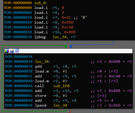
This is the part where I took a wild guess and declared that instruction 7 is loop_start and _uncond_jmp2 is loop_wrap. On this picture it means that loop counter is r7 because it is passed to loop_start. Processor associates register r7 with location loc_34 and uses this information to decrement and check r7 when execuitng instruction loop_wrap loc_34. Loops like this are used in other places too, and in the end this guess is right. For the sake of readibility, I’ll call these instructions lpbeg and lpend respectively.
With this, we know the meaning of each opcode, cool.
main
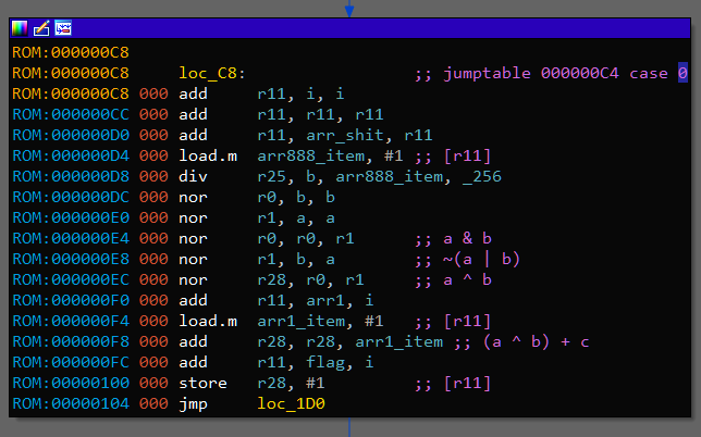
Now we can reverse engineer given binary. Let’s start with code on the last image:
There are two arrays at adresses 0xB80 and 0xCA0 from which first and second arguments are taken. Result is stored to the array 0x888. Size of elements is 4 bytes - int (or uint). 0x42 is loaded in r7 which means there would be 66 iterations. It matches lengths of argument arrays.
sub_1E0
What’s inside sub_1E0? I won’t go into much details about reverse engineering process (you just need to read code ;) ). Instead, here is sub_1E0 rewritten in Python:
def sub_1E0(r0, r1):
    arr = []
    for i in range(r0):
        arr.append(((r1 + i) % r0) + 1)
    for i in range(r0 - 1):
        for j in range(r0 - i - 1):
            if str(arr[j]) >= str(arr[j + 1]):
                arr[j], arr[j + 1] = arr[j + 1], arr[j]
    return arr[r1 - 1]
It fills an array with all numbers from 1 to r0 inclusively, sorts them lexicographically (using bubblesort) and returns r1th number. Note that filling starts with number r1 but eventually wraps to 1, and since we are sorting them all, starting from r1 does not mean anything.
Arguments r0 are very big in binary, >= 0xF0000000. We definitely can’t sort that much numbers as strings in the meaningful time, even more, we don’t have enough memory (well, if you do, I’m happy for you). Thankfully, it is kinda easy to generate already sorted stream of lexicographically sorted numbers from 1 to N. Here is my version:
def sub_1E0_on_steroids(r0, r1):
    i = 0
    num = '1'
    for i in range(r0):
        if i == r1 - 1:
            return int(num)
        t = num + '0'
        if int(t) <= r0:
            num = t
            continue
        it = 0
        while it < len(num) and num[-it - 1] == '9':
            it += 1
        if it == len(num):
            break
        if it:
            num = num[:-it]
        num = num[:-1] + chr(ord(num[-1]) + 1)
        if int(num) > r0:
            num = num[:-1]
            num = num[:-1] + chr(ord(num[-1]) + 1)
    return res
sub_1E0 is finished, let’s go back to main.
main: Part 2
After filling 0x888 array there is another loop with 66 iterations. Inside it, there is switch with 4 cases. Reading and understanding assembly code here is really enjoyable, so I leave it as an exersize. Here is Python version of all main function:
def main():
    arr_888 = []
    for i in range(66):
        arr_888.append(sub_1E0(arr_B80[i], arr_CA0[i]))
    arr_666 = []
    for i in range(66):
        a = arr_A00[i]
        b = arr_888[i] & 0xFF
        c = arr_A50[i]
        if a & 3 in (0, 1):
            arr_666.append((a ^ b) + c)
        else:
            arr_666.append((a ^ b) - c)
I bet that arr_666 contains a flag. Since we have already rewritten all the code in the real programming language, we can just run it and wait couple of minutes to get flag. You can find full solution code here. solve.cpp works 3.3 times faster on my machine - 6.5 minutes instead of Python’s 22 minutes. I expected more from C++ :^(
Also you can find full decompiled source of 0ctf2019.dll (version I worked with) here.
Update: challenge author, xiaohuajiao, published challenge sources.
Summary
We have a binary executable for custom virtual machine, and IDA processor module for this VM. By reverse engineering processor module we can recover information about VM instruction set. After that, we reverse engineer the binary and conclude that we need to run it somehow to get a flag. Since used algorithms are very inefficient, we reimplement binary logic in some programming language while performing optimizations and run the code to get a flag.
Overall, this was an extremely enjoyable task. While core idea is usual “another custom VM”, making VM description in the form of IDA processor module is pretty interesting and significally increases needed efforts to understand what’s going on. Kudos to 0ops and eee for making entertaining and challenging tasks from year to year.